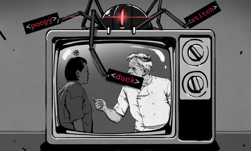
The recent flurry of videos and posts about the TVGuardian foul language filter brought back some fond memories. I was the chief engineer on this project for most of its lifespan. You’ve watched the teardowns, you’ve seen the reverse engineering, now here’s the inside scoop.
Gumby is Born
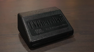
Back in 1999, my company took on a redesign project for the TVG product, a box that replaced curse words in closed-captioning with sanitized equivalents. Our first task was to take an existing design that had been produced in limited volumes and improve it to be more easily manufactured.
The original PCB used all thru-hole components and didn’t scale well to large quantity production. Replacing the parts with their surface mount equivalents resulted in Model 101, internally named Gumby for reasons long lost. If you have a sharp eye, you will have noticed something odd about two parts on the board as shown in [Ben Eater]’s video. The Microchip PIC and the Zilog OSD chip had two overlapping footprints, one for thru-hole and one for SMD. Even though we preferred SMD parts, sometimes there were supply issues. This was a technique we used on several designs in our company to hedge our bets. It also allowed us to use a socketed ICs for testing and development.
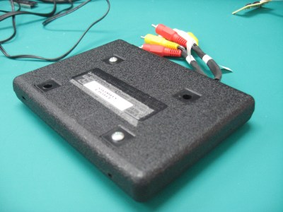
The Model 101 case received some jabs in the video, and deservedly so. The case mold was made before my involvement, but the original prototype we received was in a box that was too expensive to use in production, and it had a locking door on the back which ostensibly prevented one from unplugging the cables. At the time, our client had licensed at least one other flavor of the box called Curse Free TV ([foone] obtained one of those in their collection), and this required a mold insert to change the branding. I can’t remember the details of why there was the unused RF input, but it was either a regulatory requirement or just a consequence available modules on the market in the 1990s. My colleague fashioned a unique version for travel that was flat (without the RF modulator). We called it “Gumby Light”.
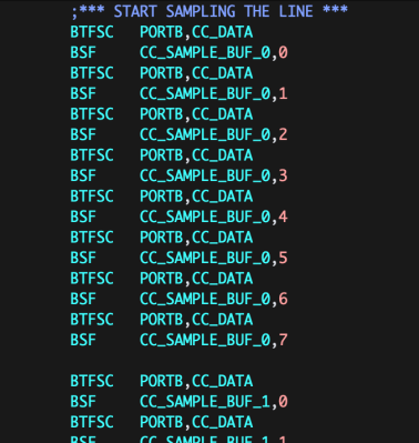
One non-obvious thing I’d like to mention about the Zilog Z86129 CC/OSD chip is that it was only half-used. The ‘129 was made to work as a stand-alone CC processor, and had no provision to access to the decoded CC data stream. Gumby’s design completely ignored this half of the chip, and used the ‘129 as an OSD generator only. Instead, the original designers thresholded line 21 data and shifted it into the PIC using really clever/evil assembly language. There were 96 pairs of bit test / bit set instructions, each executing in the same amount of time regardless of whether the CC data slicer comparator was high or low.
As [Alec] pointed out in his video, there was a switch that turned off filtering, changing the box into an external CC decoder. There was a minor demand for this functionality during all the years these products were sold, and all the designs retained this capability. Despite the FCC mandate for all new TVs to have a built-in closed caption decoder, some viewers with older or small TV sets still wanted captions and ordered these models just for that purpose.
Foul Language Dictionary
When I watched [Ben Eater] start to connect up the serial EEPROM to pull out the curse words, I was reminded of a funny incident during the production ramp-up of Gumby. The manufacturer asked to approve an alternate supplier for this EEPROM. After I checked the data sheet and a few samples, I authorized the request. Soon afterwards, they came back with a mysterious failure. We quickly tracked the problem down to the EEPROM, and realized that the data was all scrambled. But strangely, I could reprogram it and it worked fine. I clearly remember a phone call with a lady from the service company that we used to program the chips. They were following the correct procedure, getting the correct checksums, and we were baffled. There was a long pause, and she suddenly broke the silence,
“You know, it’s none of my business, but there are a some really bad words here in your hex file”.
In response to that incident, I implemented a cursory scrambling of the text, not for encryption, but so someone casually browsing the data wouldn’t be hit by a screenful of cussing. Alas, the unit [Ben] dismantled was manufactured before this.
We did ultimately find the problem with the EEPROM. The substitute had a block programming mode that put the contents into memory in a different sequence than the Microchip 93LC86 did. This was not implemented in all chip programmers, nor documented in the data sheet, but was discovered upon requesting further programming documents from the manufacturer.
Daisy and Oliver
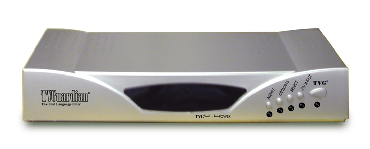
Once Gumby production was underway, the search was on for a new design that could handle new features, expanded I/O options like S-Video, digital audio, and multiple inputs. This turned out to be much more challenging than anyone thought. While chip manufacturers had various options for handling CC, they were focusing their efforts on digital video. It was clear that analog CC was on the decline. The Zilog ‘129 and its sister chips were very tempting contenders. At heart, they were really a DSP / microprocessor with custom masked-ROM firmware. We explored the option of using that in a new design with modified firmware. Gaining Zilog’s cooperation was tough, and when we learned the chip’s ROM was already filled to capacity, we gave up on that approach.
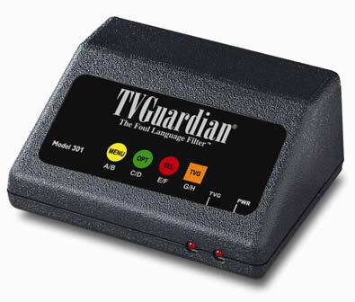
We finally stumbled on the Painter chip by Philips Semiconductor that was too good to pass up. It was a complete MCU (8051) with all the CC circuitry built-in and came with libraries for CC and user menu OSD. I wrote about this chip in my previous article on analog Closed Captions. Despite being told the part was “secret”, we eventually got permission to use it. This was my first, but sadly not last, encounter with the concept of a part and its support being so complicated that the manufacturer is very selective about who they can use it. Despite this hurdle, the team at Philips were great to work with. The Painter design formed the basis of three set top box models:
- Model 201 Oliver (2004)
- Model 301 Daisy (2004)
- Model 401 Oscar (2010)
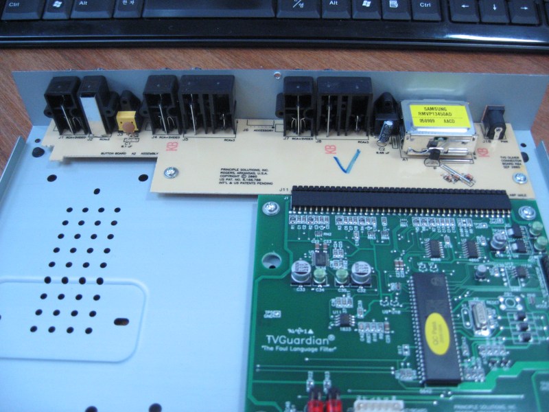
The Oliver and Daisy designs, names also of unknown origin, were both based on the Painter chip, but with differing number of inputs. Daisy only had one and Oliver had two. Digital audio turned out to be easy to mute. It was no different than muting analog audio, except using different connectors. In both cases, audio being muted by interrupting the signal with a CMOS 4066 analog switch. Originally both designs used a single board, but our contract manufacturer requested a two-board solution to save costs. The connectors were mounted on a single-sided FR1 board, and therefore the main four-layer FR4 board was able to be smaller. It surprised us that adding the inter-board connectors and the extra processing was cheaper, but that’s the way the numbers added up.
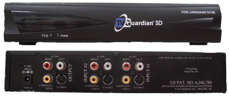
That case mold insert came in handy for the Daisy version, since we could used that area for a membrane keypad overlay. Oscar, just another name starting with the same letter as Oliver, wraps up the analog series of set top boxes. It was just a PCB re-spin, made years later in 2010, using a different enclosure and probably the very last inventory in the world of Painter chips.
Macrovision
As good as it was, the Painter solution had a few issues in a set top box application. It was designed to exist inside a TV set, and required stable horizontal and vertical sync signals. We had to make this external to the chip. This would normally be a straightforward design but was complicated by the need to tolerate Macrovision’s Analog Copy Protection (ACP) scheme of the day. ACP existed in various flavors, all of them inserted extra sync pulses of varying amplitude in the vertical blanking interval (VBI) of the video. Ostensibly, these pulses wouldn’t mess with the high-Q tank synchronization circuit of a television set, but caused havoc on the sync and AGC circuits of VHS recorders. The PIC design we inherited in Gumby tolerated Macrovision in firmware, but wasn’t perfect. This worried me, because ACP methods were numerous and subject to change. I didn’t want to test against all different forms that the set top boxes might encounter in the field. So I chickened out on this part of the circuit design and bought a solution off-the-shelf in the form of the Elantec (now Renesas) EL1883 sync separator chip, passing the buck as it were.
A second but minor issue was that like the Zilog chip, normal CC module usage was as a stand-alone black box with no access to read / modify the data stream. But this being implemented in firmware, it was easy to hack around. We were able to grab and alter the data before presenting it to the CC decoder function.

The Painter support firmware provided by Philips was not entirely pre-compiled libraries. There were some aspects of the build that required re-compilation of certain proprietary source code files, depending on features needed by the application. Philips provided these files as encrypted source code and a decryption tool in the form of a Windows DLL named C51_RD.dll. They cooperated with Keil so that the compiler knew to make use of this decryption algorithm whenever a file with an .ec extension was encountered. I presume this ability must no longer be part of Keil, since I cannot find any mention of it online in 2022.
On the Trailing Edge
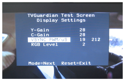
While the ‘1883 solved the Macrovision problem, there was one hiccup. The leading edge of the VSYNC signal was precisely specified, but the falling edge was not — in other words, the pulsewidth of VSYNC was not controlled. In fact, it varied quite a bit from chip to chip. This was not good, because the Painter’s CC decoding synchronized on the trailing edge of VSYNC. It turned out that the pulse width could be tweaked by changing the value of an external resistor Rset.
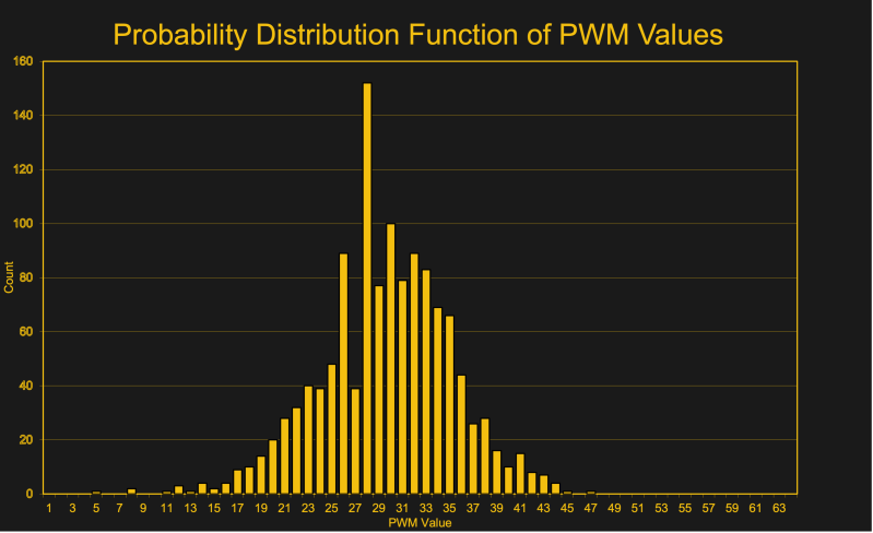
We dealt with this by adding a factory calibration step. The Painter would measure and display VSYNC pulse width the operator, and the operator would adjust the width up and down using two test fixture buttons until the pulse width reached the desired value, the Painter changing the effective Rset value using a PWM output. We collected over a thousand of these settings during the first production in 2004 in order to characterize the spread, both out of curiosity and at Elantec engineering’s request.
Fully Digital? Project Herbert
The set top box design remained stable for many years and the project eventually wound down. The advent of digital television and video made the technology in these units obsolete. Or so I thought. In 2010, I was asked to undertake a new design using HDMI video. The TVGuardian inventor [Rick Bray] had discovered that most HDMI video sources continued to provide simultaneous analog composite video output with the CC signal. Thus began the design of a new set top box I named Herbert — a random name starting with an “H” standing for HD video.
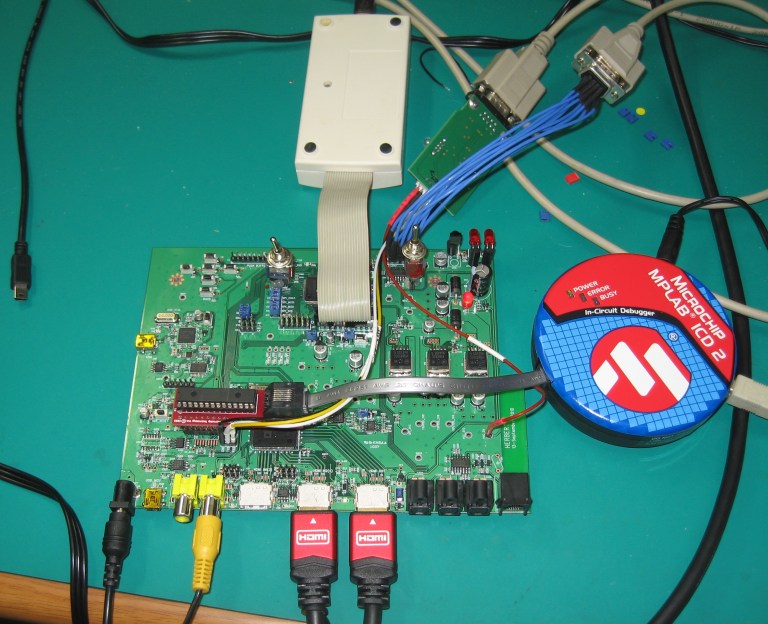
Entering the world of HDMI video designs is not for the faint-hearted. The entry price is painful, with steep annual membership required in both the HDMI and HDCP organizations along with per-unit royalties — those were in fact actually reasonable. None of the available HDMI chips had support for CC, since there is no CC data transmitted over the HDMI interface, a point I discussed in this article. We eventually selected the ADV7623 from Analog Devices, an HDMI repeater chip with support for OSD text and icons. This was one of those parts that came with the promise of minimal or no support from the manufacturer, especially since I was trying to use it in a way it wasn’t intended — that is, dynamically changing text instead of fixed OSD.
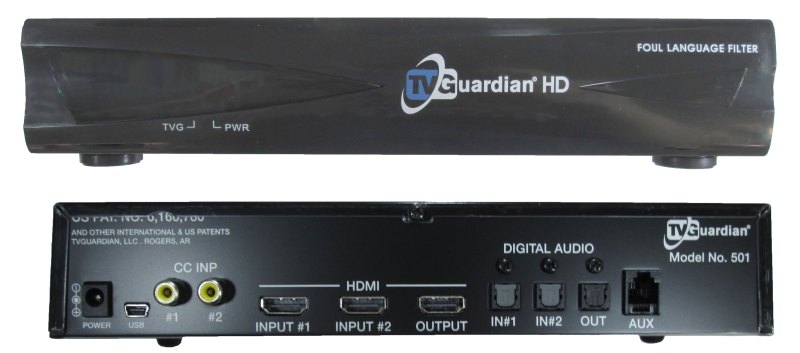
The Analog Devices engineers turned out to more helpful that we expected. While it was a long and frustrating hack, I eventually figured out the various hidden and undefined behaviors of the OSD system and made it work. Besides the original goal of making a CC decoder, another client in Korea wanted to use this chip to generate a scrolling text crawl along the bottom of the screen. Naturally, he wanted both English and Korean text (Hangul). That was another fun hack as well, generating foreign language glyphs and moving them smoothly one pixel at a time across the screen. The Herbert platform supported the TVG Model 501 product, and a few other niche applications that needed dynamic OSD overlay on HDMI.
Not a Telephone Jack
One interesting accessory I designed, but was never sold, was a center-channel audio muting switch for use with surround sound systems. There is an 6P6C modular connector on the back of Herbert providing auxiliary power and muting signals for this accessory. The idea here is that 95% of movie dialog comes in the center channel speaker, and the mute is less jarring when only the words are muted and other background sounds are preserved. I avoided needing to decode, tinker with, and re-encode the surround sound signals by just switching the wires going to the center-channel speaker. However, this was a pretty expensive module — it used relays to mute the audio, and switched in 8-ohm power resistors when muting in order to trick the amplifier into thinking the speaker was still connected. Otherwise, some amplifiers would sense a fault and shut down.
“Wow You” and “Oh Crud”
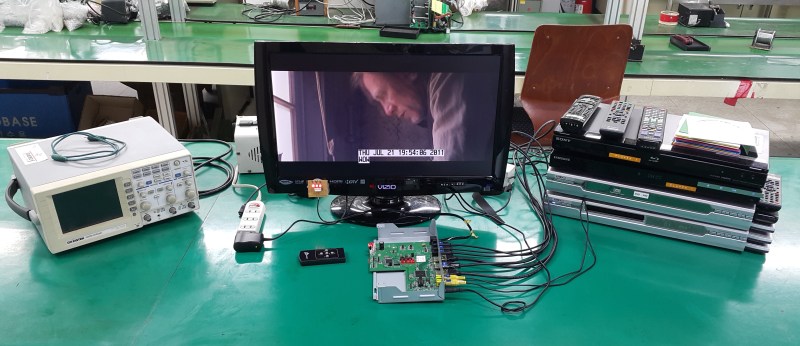
Factory testing needed a long repeatable source of closed captioning which included filthy words. In the very beginning, the factory used VHS copies of South Park animated sitcoms. Later on, I experimented with various custom VHS tapes, DVD movies, and even a computer with dual CC generator cards installed. I finally settled on making two custom DVDs. These had a video color bar test pattern and line 21 data containing words that alternated between cussing and not. These are the WOW YOU and OH CRUD test discs — two different discs/phrases were used so the operator could distinguish channel 1 from channel 2. A full setup for testing Herbert input used two DVD/BD players providing HDMI video, and two DVD players containing the CC discs generating the composite video. For outputs, a monitor was used to check the HDMI output, an oscilloscope with an optical to coaxial digital adaptor was used to check the muting, and a pair of LEDs were used to check the never-used auxiliary connector.
Bunny and Project Sally
All these experiences with closed designs and specialty chips really bothered me, and I continued searching for alternatives. On the HDMI side, I was really interested in applying the techniques developed by [Bunnie Huang] for NeTV, which we covered back in 2012. I experimented with his development kit, but alas I could not convince any of our clients to take the perceived legal risk of using his approach in a product.
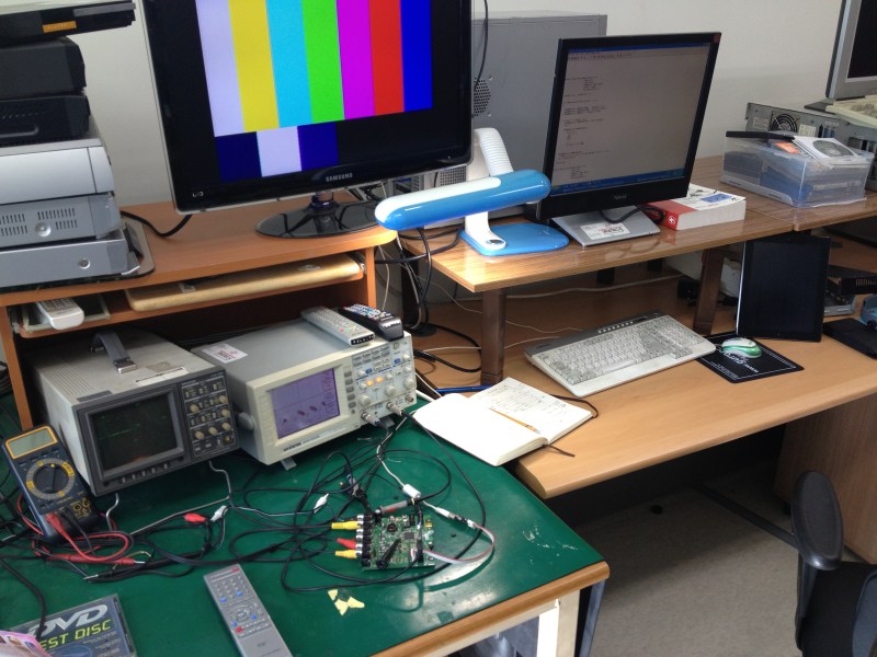
I had more success with an internal design I called Sally — boringly named because “S” stood for for SD video. I was inspired by various Arm-based projects which were generating VGA signals directly for retro games. But it seemed to me that these wasted a lot of memory storing with pixel buffers. Then one day I realized that a timer-counter register could serve as the destination for a DMA transfer (on an LPC1768 at least). This meant you could store pixel data much more efficiently in a run-length encoding manner. A line of pixels was just a short buffer of amplitudes and timer durations. I built and demonstrated this approach, successfully generating test video patterns or CC signals. It could also synchronize with an incoming video signal for doing overlay of menus and CC data. Alas, this design never made it into production, but I may revisit this in a future writeup.
Recent Videos and Posts about TVGuardian
- [Alec Watson]’s Technology Connections video “This TV gadget censors bad words with 1980’s tech”
- [Ben Eater]’s follow-on video entitled “Hacking a weird TV censoring device”, which we covered here
- [RetroStuff]’s post “TVGuardian 101 and 201 Foul Language Filters” (actually from last year)
- [foone]’s extensive experiments with various TVG models
The Story Behind the TVGuardian Curse Catcher
Source: Manila Flash Report
0 Comments