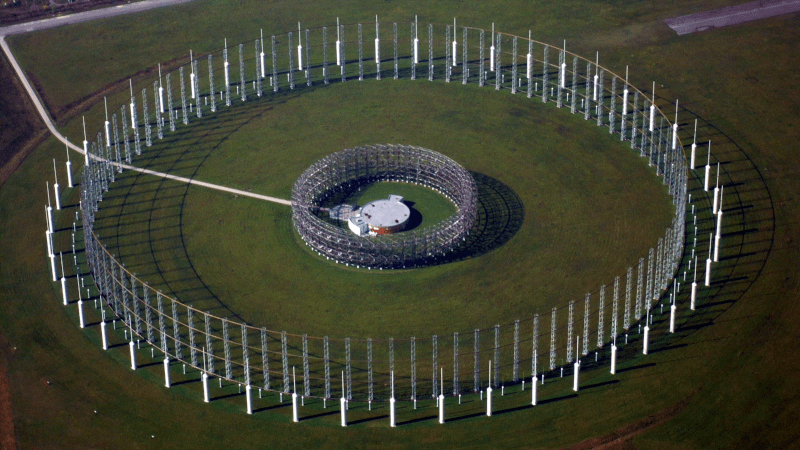
With a UHF antenna, it is easy to rotate a directional antenna to find the bearing to a transmitter. But at HF, it is more common to use an array of antennas that you can electrically switch as well as analyze the phase information between the elements. [Ringway Manchester] has a look at the “elephant cage” antenna used by the US Iron Horse listening network from the 1950s. You can see a video about the giant antenna system, the AN/FLR-9.
Technically, the ring of concentric antenna elements forms a Wullenweber antenna. The whole thing consists of three rings built on a ground screen nearly 1,500 feet across. The outer ring covers from 1.5 to 6 MHz or band A. The band B ring in the center covers 6 to 18 MHz. The inner ring covers band C which was from 18 to 10 MHz. Band A was made up of 48 monopoles while band B used 96 elements. The much smaller band C elements were 48 pairs of horizontally polarized dipoles.
These listening posts could, together, locate an HF signal up to 4,000 nautical miles away. The Wullenweber design, as you may have guessed from the name, originated with the German navy during World War II. It found use in several other systems, although they are relatively rare today, with all of the AN/FLR-9 sites gone.
Cold war hardware is always interesting even if sometimes terrifying. If you think a giant shortwave direction finder is high-tech, you should check out how the Russians bugged IBM Selectric typewriters for a long time undetected.
Cold War Listening Post Antennas
Source: Manila Flash Report
0 Comments