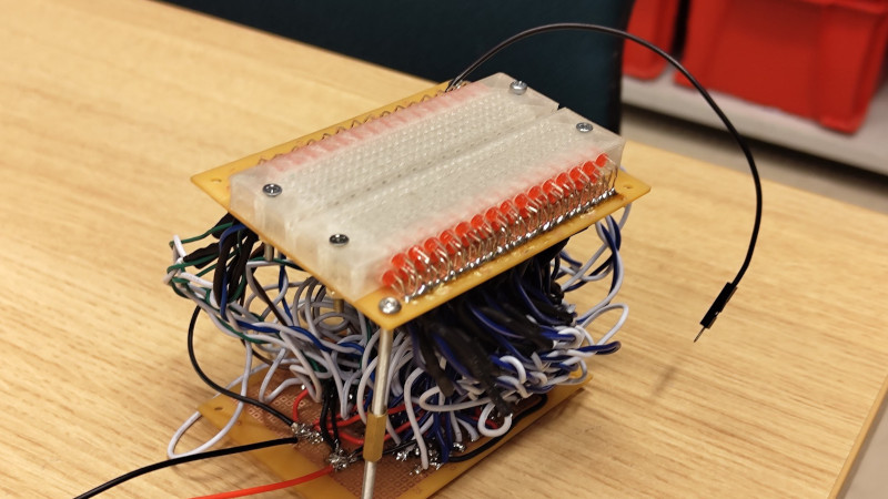
Most Hackaday readers will no doubt at some point used a solderless breadboard for prototyping. They do the job, but sometimes their layout can be inflexible and keeping track of signals can be a pain. There’s a neat idea from [rasmusviil0] which might go some way to making the humble breadboard easier to use, it’s a breadboard in which each line is coupled via an op-amp buffer to an LED. In this way it can be seen at a glance some indication of the DC voltage present.
It’s an idea reminiscent of those simple logic probes which were popular years ago, but its implementation is not entirely easy. Each circuit is simple enough, but to replicate it across all the lines in a breadboard makes for a huge amount of quad op-amp chips stuffed onto one piece of stripboard as well as a veritable forest of wires beneath the board.
The effect is of a breadboard crossed with a set of blinkenlights, and we could see that for simple digital circuits it could have some utility if not so much for higher frequency or analogue signals. Certainly it’s an experiment worth doing, and indeed it’s not the first tricked out breadboard we’ve seen.
Op-Amp Challenge: Light Up Breadboard Shows Us The Signals
Source: Manila Flash Report

0 Comments