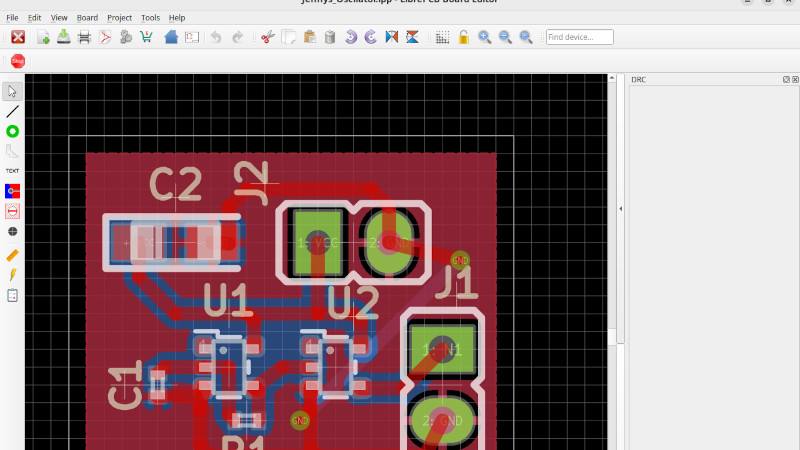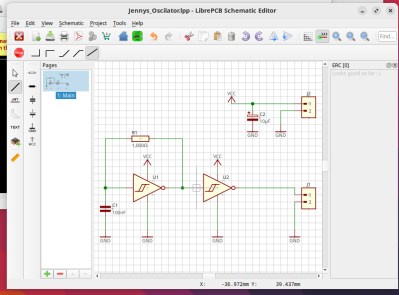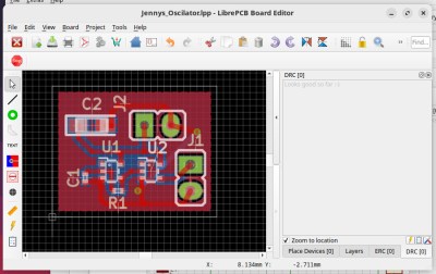
Nearly three years ago at the start of 2020 and before the pandemic hit, we took a look at an up-and-coming player in the world of PCB design. LibrePCB is by no means as old as the more established players, but at the time it was joining the ranks of open-source EDA packages with its first early stable releases. It showed a lot of promise but was still a little rough around the edges back then, but in the years since it’s advanced to the extent that in September they released version 1.0. That’s a significant moment for any open source package, so it’s time to return and take another look. It’s a cross-platform package with builds available for Linux, Windows, MacOS and FreeBSD, of which I needed the Linux version. There are one or two options to choose from, I went for the appImage as probably the least trouble. Very quickly I was in a new EDA package, and I set out to make a simple Schmitt trigger oscillator as a test project.
Back with another oscillator

In my review of the earlier version I made the observation that the user interface was particularly intuitive for me as a former Eagle user, and in that respect it remains a very easy package to get to know. It fortunately lacks the arcane tricks which users have to learn that plague so many CAD and EDA packages, I fount it all very quick to get back into and soon had my project set up and was creating a schematic. If there was a feature I wish it had at this point it would be to import projects from other packages, in particular Eagle. However it’s understood that this is no easy task, and shouldn’t stop an ex-Eagle user from diving in.
There is now a range of libraries that can be imported into the library manager covering common parts and boards, and I’m guessing that the selection will grow over time as more people use it. An interesting point to note is that the library manager has version control support, so you can mange a library held in a git repository from it.

The error checking works on the fly as you create, and quickly alerts you to such things as unconnected nets, or in the board editor, DRC failures. I was very quickly able to fix all the problems in my schematic, and once I had a layout it was made very simple to work through each one and fix it. A Schmitt trigger oscillator is hardly a complex circuit so I was done pretty quickly, but it was still enough to put the software through its paces.
LibrePCB has a model of treating footprints and schematic symbols as separate objects which are brought together to make a part, and I returned to the 2N3904 through-hole transistor I made last time. There’s now an arc tool, so the only gripe I found is now gone. It also supports a 3D view for which I had no model handy, but here the process was also pretty straightforward.
If you’re an Eagle user, take note

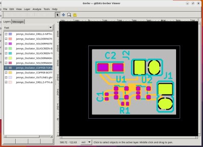
All that remained was to export my Gerbers and take a look in gerbv, where they appear exactly as I’d expect. There’s also the option to upload them directly to a PCB fabricator, with a donation from the fab going to LibrePCB. Currently the selection is limited to Aisler and PCBway, from which we’re guesisng most will be satisfied.
So then, LibrePCB version 1.0. I advised waiting before using it in anger last time, because there were plenty of areas that needed attention back then. I think that in this version they’ve delivered an extremely usable EDA package, and while it’s probably not going to tempt a huge number away from some of the more established players I think it’s a sure-fire winner for ex-Eagle users despite not having an import feature for Eagle projects. I like it so much I’m keeping it on my machine, and I’m going to use it for my projects.
Review: LibrePCB Hits Version 1.0
Source: Manila Flash Report
0 Comments